In the Era of AI Optical Communication, Circulators Become the "Invisible Key" to Unlocking Computing Power Transmission
In the Era of AI Optical Communication, Circulators Become
the "Invisible Key" to Unlocking Computing Power Transmission
The core requirement of AI optical communication is "high-speed transmission + efficient scheduling", and circulators are precisely the key components to achieve this goal. In the scenario of AI data center interconnection, OCS (Optical Circuit Switch) has become the core support for intelligent computing clusters by virtue of its advantages of no electro-optical conversion, low latency, and low power consumption. As a core component of the OCS system, circulators can realize single-fiber bidirectional transmission, directly halving the number of ports and optical fibers of the OCS system, and significantly reducing deployment costs. This is also one of the key supports for Google's TPU clusters to achieve a 40% reduction in power consumption and a 30% reduction in capital expenditure after introducing OCS.
Moreover, circulators also play an irreplaceable role in AI-enabled ultra-high-speed optical transmission. Recently, the industry has realized the neural network equalization technology based on AI transfer learning, which has achieved a breakthrough in ultra-high-speed transmission of 254.7Tb/s over 200km single-mode optical fiber. Behind this breakthrough, the precise signal isolation and support of circulators are indispensable. The low insertion loss characteristic of circulators (typical value within 1.0dB) reserves sufficient link budget for AI-driven multi-band coordinated transmission (S+C+L). Combined with the error correction of AI algorithms, the total throughput of the transmission system is increased by 11.7%, which perfectly meets the extreme requirements of large AI models for high bandwidth and low latency.
Core Composition of Circulators
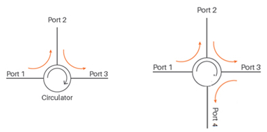
An optical circulator is a core passive component in optical communication that enables unidirectional cyclic transmission. Its core lies in utilizing the Faraday magneto-optical effect to achieve non-reciprocity, allowing light to transmit only in the fixed direction of 1→2→3→1 while isolating reverse transmission.
Core Components (Three-Port Typical Structure)
An optical circulator is composed of the following key optical components with precise assembly:
- Fiber Collimator
Function: Convert divergent light in the optical fiber into parallel collimated light, and reduce the coupling loss of subsequent optical components.
Position: Configured at the front end of each input/output port.
Polarizing Beam Splitter/Combiner (PBS/PBC)
Function: Decompose the input light into two orthogonally polarized lights, i.e., horizontal (o-light) and vertical (e-light); in the reverse direction, combine the two light beams into one for output.
Role: Realize the spatial separation and recombination of polarization states, and serve as the foundation for optical path switching.
- Faraday Rotator (Core Component)
Material: Magneto-optical crystals such as Yttrium Iron Garnet (YIG).
Principle: Under the action of an external constant magnetic field, the polarization plane of the transmitted linearly polarized light is rotated by a fixed 45°.
Key Characteristic: The rotation direction is independent of the light propagation direction (non-reciprocity), which is the physical origin of unidirectional transmission.
- λ/2 Waveplate
Function: Perform reciprocal 45° rotation on the polarization state (the rotation direction changes with the light propagation direction).
Role: Cooperate with the Faraday rotator to achieve forward conduction and reverse isolation.
- Reflector / Prism
Function: Change the propagation direction of the light beam and realize the spatial optical path connection between multiple ports.

Working Principle (Taking the Three-Port Circulator as an Example)
The working process of an optical circulator can be summarized as: Polarization Separation → Non-Reciprocal Rotation → Polarization Combination → Directional Output.
Forward Transmission (1→2)
Light enters from Port 1 and is converted into parallel light by the collimator.
It is incident on the PBS, where it is split into two orthogonally polarized beams—horizontal (o-light) and vertical (e-light)—which propagate along different paths.
Both beams pass through the Faraday rotator simultaneously, and the polarization plane of each is non-reciprocally rotated by 45°.
Subsequently, they pass through the λ/2 waveplate, and their polarization planes are reciprocally rotated by another 45°.
Total effect: The polarization states of the two beams are each rotated by a total of 90° (o-light → e-light, e-light → o-light).
The rotated two beams reach the second PBC, where they are recombined into a single beam and output from Port 2.
Reverse Isolation (2→1)
Light enters from Port 2, and after collimation, it is split into o-light and e-light by the PBS.
The two beams pass through the λ/2 waveplate in the reverse direction, and their polarization planes are reciprocally rotated by 45° (the direction is opposite to that of forward transmission).
Then they pass through the Faraday rotator, and their polarization planes are non-reciprocally rotated by 45° (the direction is the same as that of forward transmission).
Total effect: The polarization states of the two beams cancel each other out, with a total rotation of 0°, restoring to the original polarization state.
When the two beams attempt to pass through the first PBS, they cannot be coupled into Port 1 due to polarization state mismatch; instead, they are directed to Port 3 for output.
Circulating Characteristics
Input at Port 1 → Output at Port 2
Input at Port 2 → Output at Port 3
Input at Port 3 → Output at Port 1
All reverse paths are isolated, enabling unidirectional circulation.
Core Physical Effect: Faraday Magneto-Optical Effect
Faraday Effect (Magneto-Optic Rotation): When linearly polarized light passes through a magneto-optical medium along the direction of a magnetic field, its polarization plane rotates, and the rotation direction is independent of the light propagation direction (non-reciprocal).
Physical Mechanism: Linearly polarized light can be decomposed into left-handed and right-handed circularly polarized light; the magnetic field causes the medium to have different refractive indices for the two (circular birefringence), resulting in differences in their propagation speeds. After exiting the medium, the phase difference leads to the rotation of the combined polarization plane.
Rotation Angle Formula: θ = V·B·L
θ: Polarization Plane Rotation Angle
V: Verdet Constant (a material property; magneto-optical crystals such as YIG and TGG have large V values)
B: Magnetic Induction Intensity Along the Optical Axis
L: Propagation Length of Light in the Medium
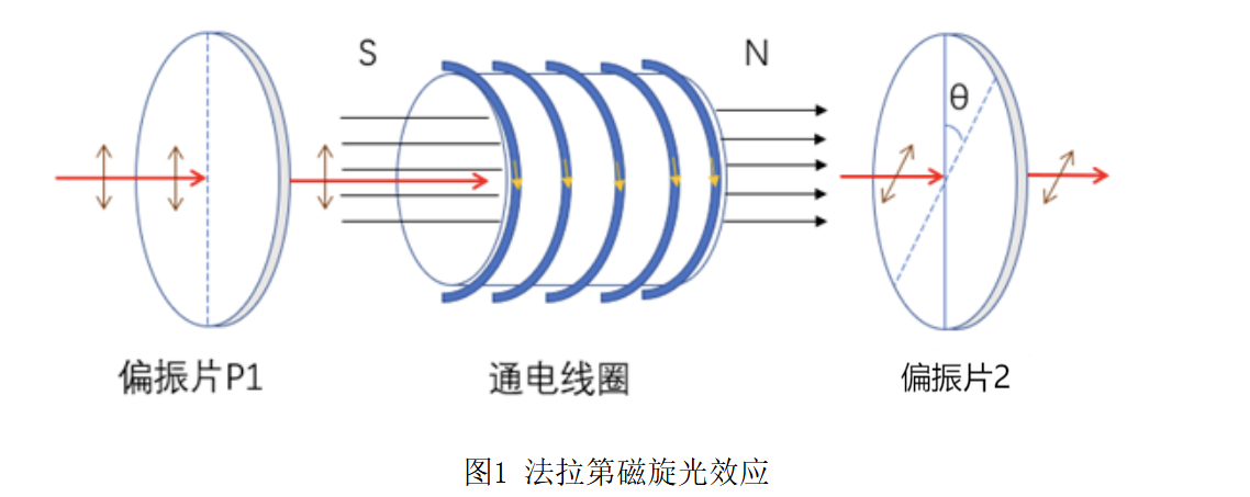
Key Characteristic: Non-Reciprocity — When light passes through in the forward/reverse direction, the rotation direction of the polarization plane is the same and the angles are superimposed (the opposite is true for natural optical rotation).
For further research, according to the propagation law of electromagnetic waves in magneto-optical materials, when linearly polarized light passes through a magneto-optical crystal of a certain thickness, its rotation angle is:
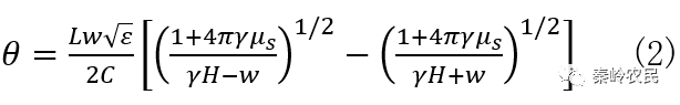
w: Frequency of light;ε: Characteristic constant of the material;C: Speed of light
γ: Gyromagnetic ratio of the material;H: External magnetic field strength
μs: Saturation magnetic field strength
It can be seen from Equation (2) that the magnitude of the rotation angle θ is affected by the gyromagnetic properties, length, operating wavelength of the magneto-optical material, and the magnetic field strength. The longer the material and the greater the magnetic field strength, the larger the rotation angle will be. In addition, the magnitude of the rotation angle θ is also affected by the ambient temperature; for most crystals, an increase in temperature will lead to a decrease in the rotation angle.
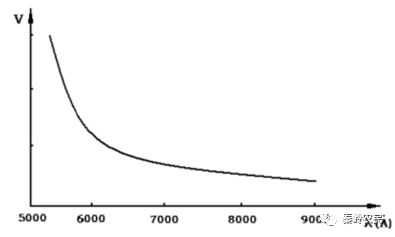
The Faraday effect also exhibits optical rotatory dispersion, meaning the Verdet constant varies with wavelength. When a beam of white linearly polarized light passes through a magneto-optically rotating medium, the rotation angle of the polarization plane of violet light is larger than that of red light—this is optical rotatory dispersion. Experiments show that the Verdet constant V of magneto-optically rotating substances decreases with the increase of wavelength. As shown in Figure 2, the optical rotatory dispersion curve is also called the Faraday rotation spectrum.
Core Value in Optical Communication
Single-Fiber Bidirectional Communication: Transmits uplink and downlink signals simultaneously in a single optical fiber without mutual interference.
WDM System: Used in Optical Add-Drop Multiplexing (OADM) to realize the adding and dropping of wavelength signals.
Optical Amplifier: Cooperates with EDFA (Erbium-Doped Fiber Amplifier) to achieve bidirectional amplification and isolation of signals.
Dispersion Compensation: Guides optical signals to pass through the compensation fiber unidirectionally in the dispersion compensation module.
Circulators Available from Hirundo:
|
Parameters |
3 Ports |
4 Ports |
Unit |
||
|
Grade |
P |
A |
P |
A |
- |
|
Directivity |
Port 1 to Port 2 to Port 3 |
Port 1 to Port 2 to Port 3 to Port 4 |
- |
||
|
Center Wavelength(λc) |
1310 or 1550 |
1310 or 1550 |
nm |
||
|
Operating Wavelength Range |
λc±30 |
λc±20 |
nm |
||
|
Typical Peak Isolation |
≥50 |
≥50 |
dB |
||
|
Min Isolation @23℃, full wavelength |
≥40 |
≥38 |
dB |
||
|
Typical Insertion Loss@23℃ |
≤0.6 |
≤0.8 |
≤0.7 |
≤0.9 |
dB |
|
Insertion Loss |
≤0.8 |
≤1.0 |
≤0.9 |
≤1.1 |
dB |
Influencing Factors
The parameter performance of a circulator (such as isolation, insertion loss, bandwidth, etc.) is affected by many factors, which can be divided into four core categories:
Core Material Properties (Most Critical Factor)
Microwave Ferrite Material: Its gyromagnetic properties (such as saturation magnetization, permeability) directly determine the non-reciprocal transmission capability of the circulator. Insufficient material purity and uniformity will lead to decreased isolation and increased insertion loss.
Substrate and Conductor Materials: The dielectric constant and loss tangent of the substrate affect signal transmission efficiency; the conductivity of conductor materials (such as copper, gold) directly affects insertion loss and power capacity.
Structural Design Parameters
Port Structure: Differences in three-port/multi-port design and microstrip/coaxial/waveguide structures affect bandwidth and power capacity (e.g., waveguide circulators are suitable for high-power scenarios, while microstrip circulators are more suitable for miniaturization).
Dimensional Accuracy: The processing accuracy of the internal conductor spacing of the device and the size of the ferrite chip can cause signal crosstalk, reduce isolation, and affect parameter stability.
Process Manufacturing Level
Assembly Process: The bonding accuracy between the ferrite chip and the substrate, as well as the port welding quality. Gaps or cold solder joints will introduce additional losses and damage the unidirectional signal transmission characteristics.
Coating Process: The thickness and uniformity of the coating on the conductor surface affect the conductivity efficiency, which in turn affects the insertion loss and device lifespan.
Special Processes: The quality of application of processes such as LTCC (Low-Temperature Co-fired Ceramic) affects the miniaturization degree and parameter consistency of the circulator.
External Operating Environment
Temperature: Extreme temperatures (e.g., -40℃ to +125℃ in automotive-grade scenarios) can change the magnetic properties of ferrite materials, leading to parameter drift and affecting stability.
Frequency Range: The circulator’s parameters (such as isolation and insertion loss) change with the operating frequency; exceeding the designed frequency band will lead to a significant drop in performance.
External Interference: A strong electromagnetic environment can interfere with signal transmission, indirectly affecting the circulator’s parameter performance, which requires optimization with shielding structures.